Desktop Plastic Injection Molding Machine
The goal of this project was to develop a compact desktop plastic injection molding machine tailored for prototyping and small-scale production. Unlike traditional models relying on pneumatic systems, my design prioritizes portability and noise reduction, making it an excellent fit for smaller workshops!
How does it work?
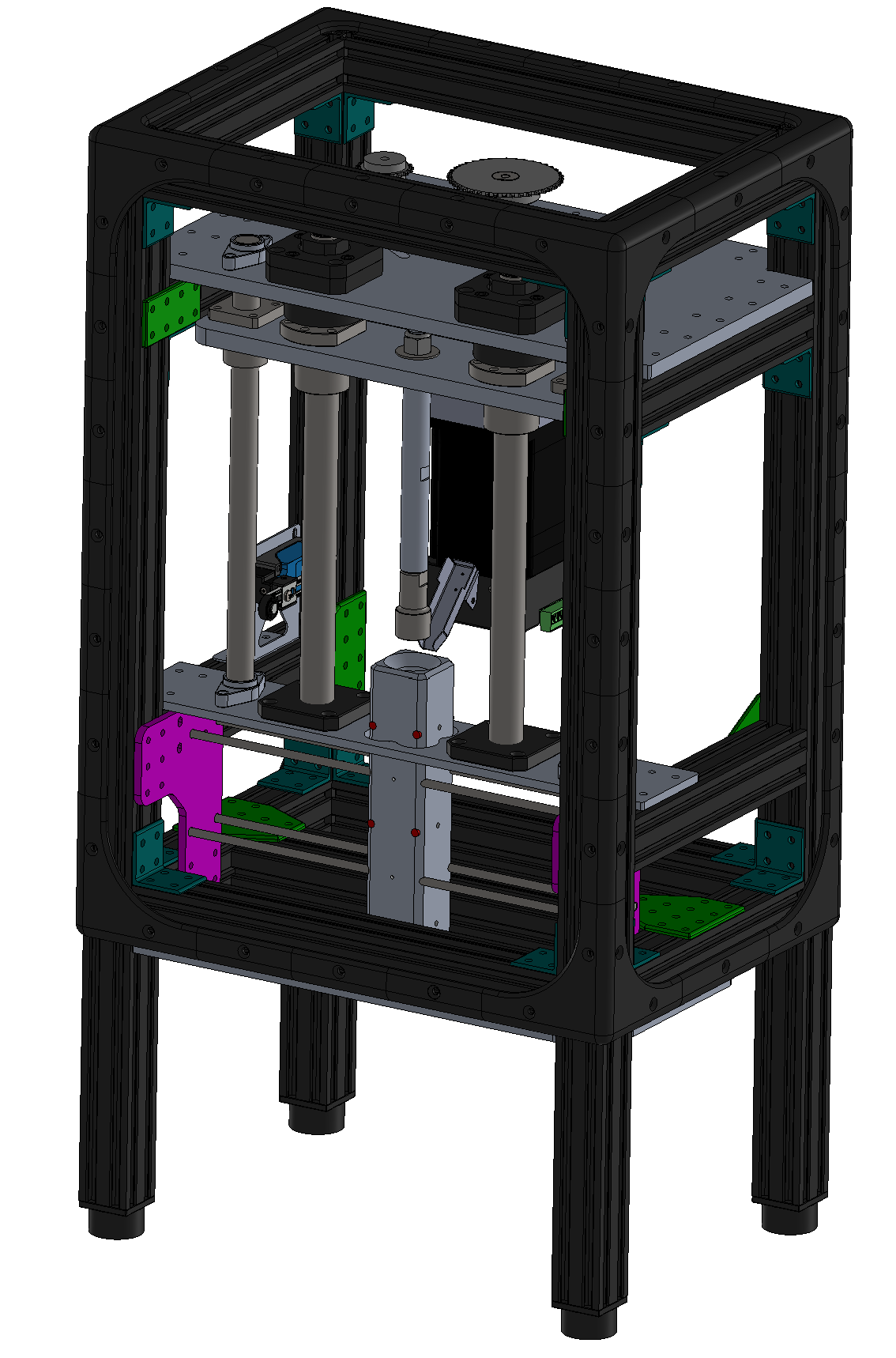
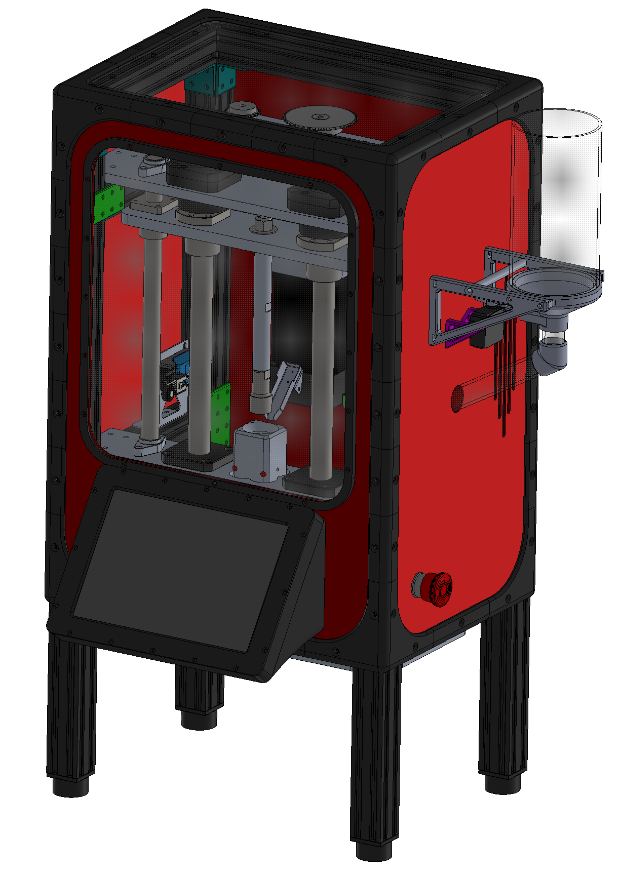
A single brushless DC motor is linked to the ball screws via a chain, ensuring synchronous movement of the screws. This synchronized motion enables the plunger to move smoothly up and down. The barrel is heated to the required temperature for melting the thermoplastic material using heat cartridges, with temperature control managed by three thermistors and a PID algorithm. To prevent overextension, two limit switches are installed to detect when the plunger reaches its upper and lower positions, automatically stopping the motor. The feeding mechanism is automated with a servo to precisely deliver the required quantity of pellets for filling the mold in use.
CFD & FEA SIMULATIONS
Before moving on to manufacturing, I needed to make sure the CAD design was optimized. So, I ran some simulations—CFD and FEA—to figure out a couple of things: How many heat cartridges were necessary to evenly heat the barrel and prevent temperature fluctuations, and how thick the metal plates needed to be to protect the machine from damage.
How many heat cartridges do I need?
After checking out the CFD simulation results for the barrel cross-section, I noticed that having either 8 or 6 cartridges made just a 0.5ºC difference (orange versus green). As anticipated, opting for 8 cartridges would provide a more even outcome. Yet, I figured that a 0.5 ºC variance wouldn't noticeably affect the machine's performance or the quality of the injected parts. Choosing 6 cartridges not only made the assembly simpler but also cut down the cost by -$70.
What thickness should I aim for with the pressing plate?
Initially, I went for Aluminum 6061-T6 at 10mm thickness to push the plunger. However, when I ran the FEA simulation, it showed that under maximum torque, the motor could deform the plate plastically. To tackle this, I had three main choices:
1) Switching to a material with a higher yield strength seemed like a solution, but it would significantly increase raw material costs.
2) Changing the plate design by moving the ball screws closer to the plate’s center was an option, but it would require major modifications to the machine.
3) Adjusting the plate's thickness while keeping the same material and dimensions seemed like the best option, as it wouldn't impact cost or design much.
MANUFACTURING
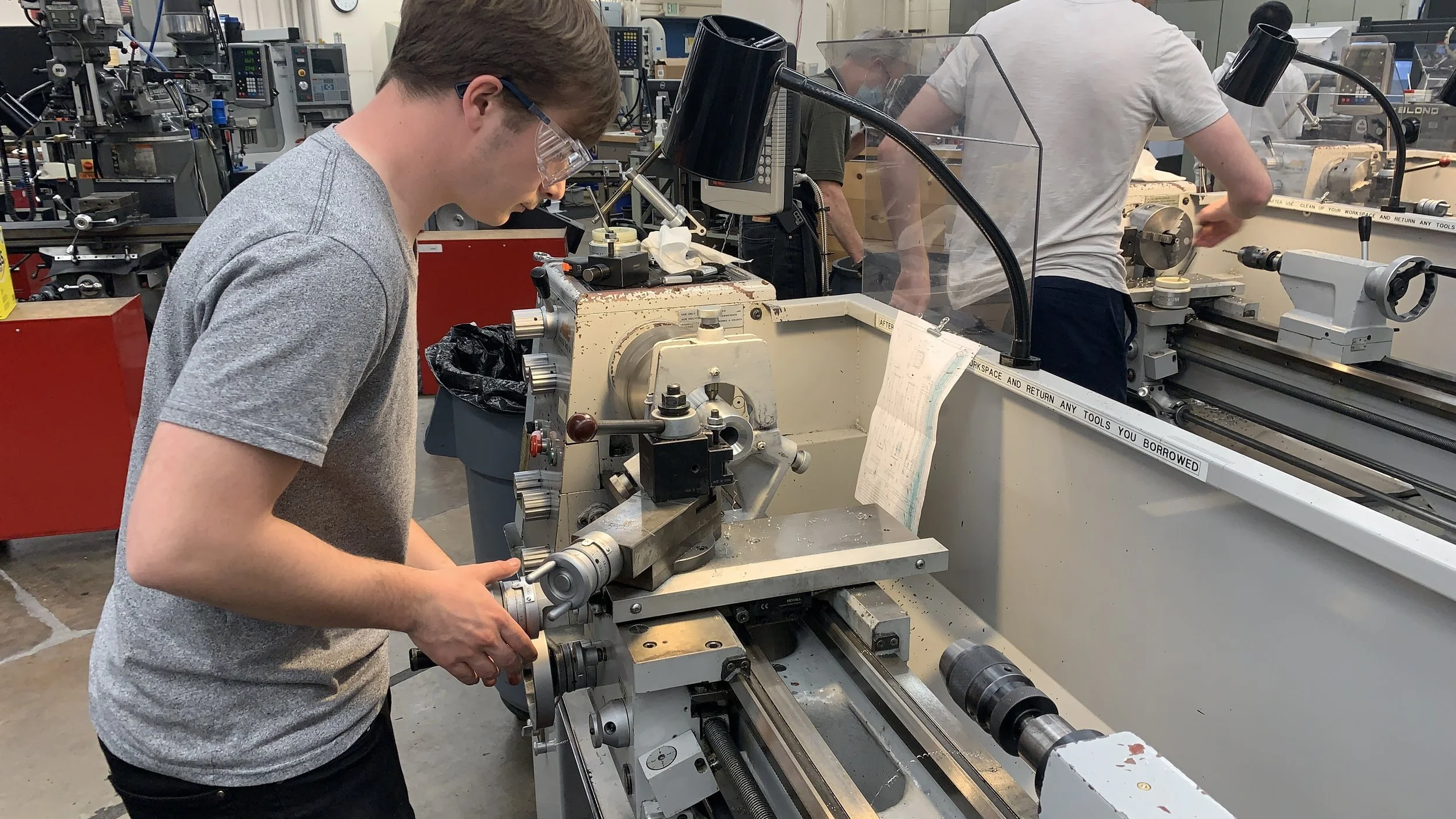
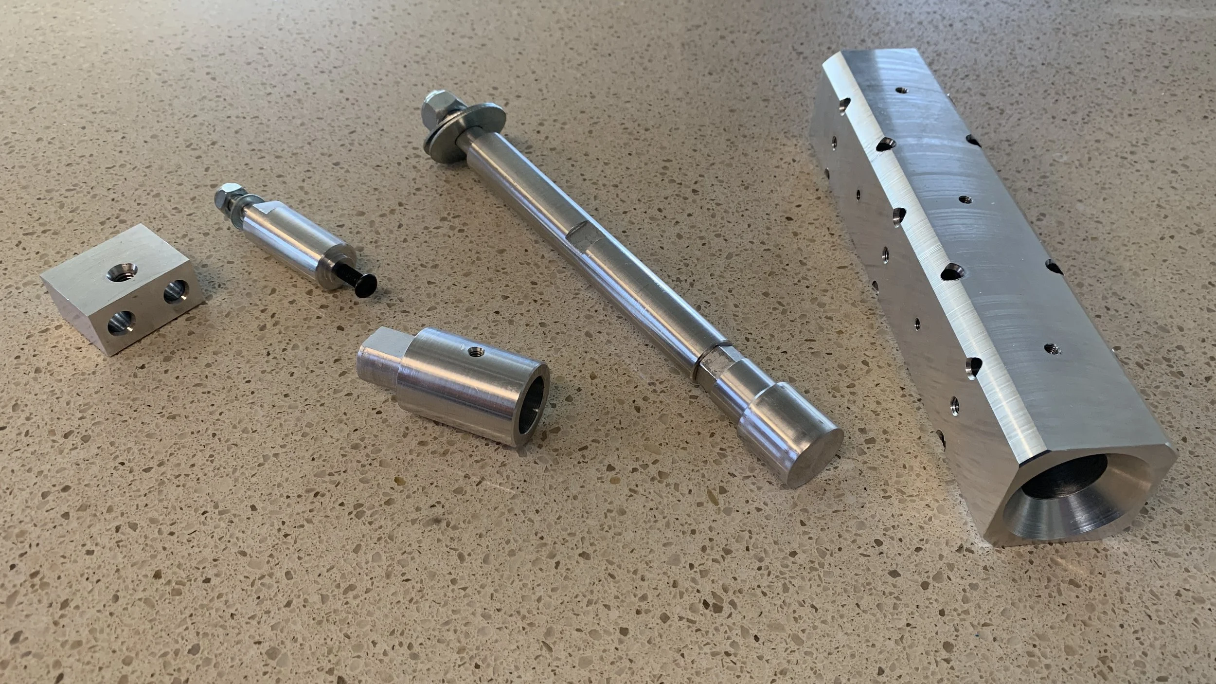
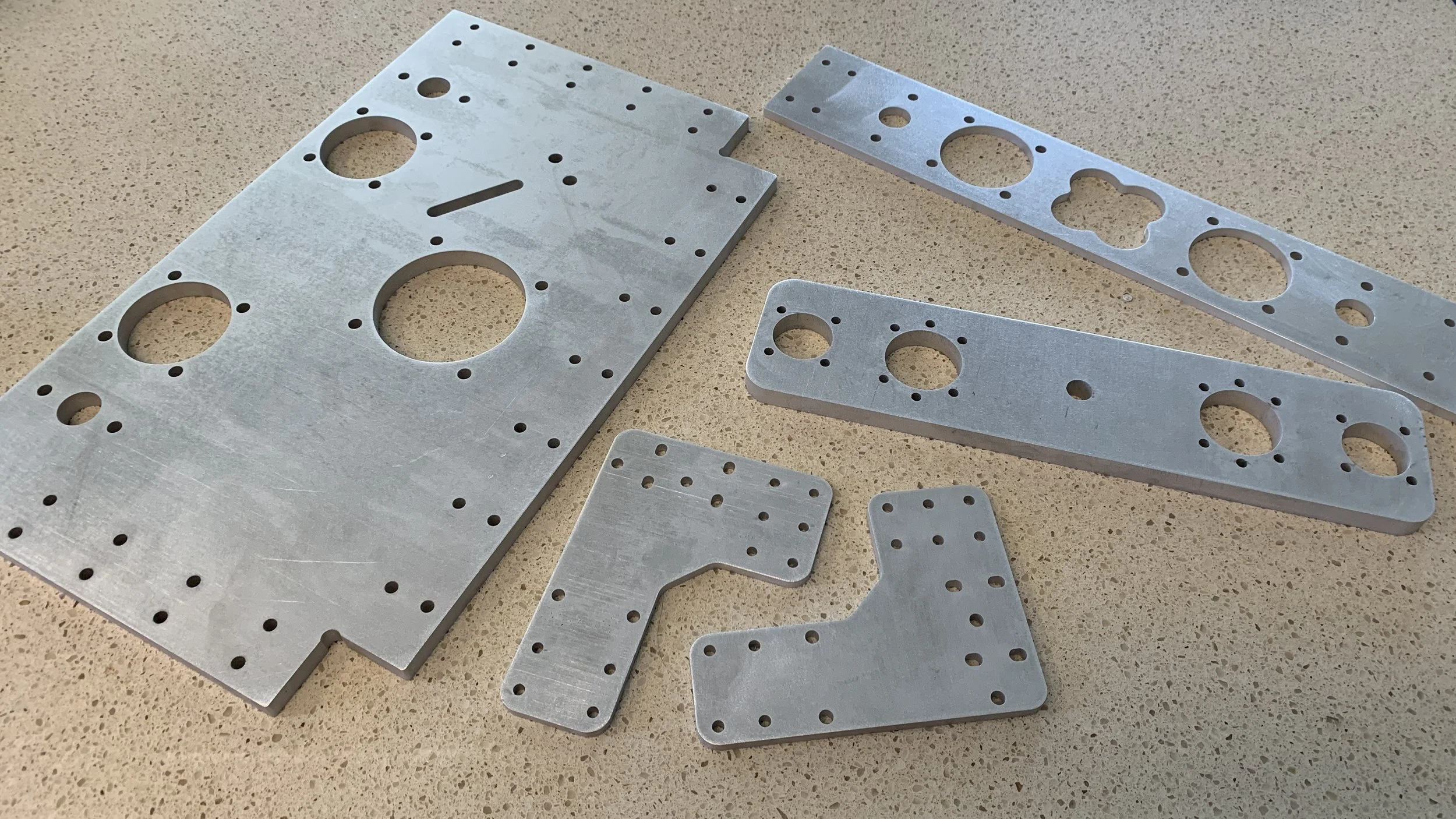
After finishing the CAD and 2D drawings, it was time to dive into the manufacturing process. I personally machined all the parts, using the following manufacturing process:
