How it all started
Everything started in 2019 when I was only a sophomore student. At that moment, I felt it was time to start my entrepreneurial journey.
I wanted to offer a CNC router at an affordable price for the maker community. The vast majority of options on the market were in the $3,000 range, making it unaffordable for many makers.
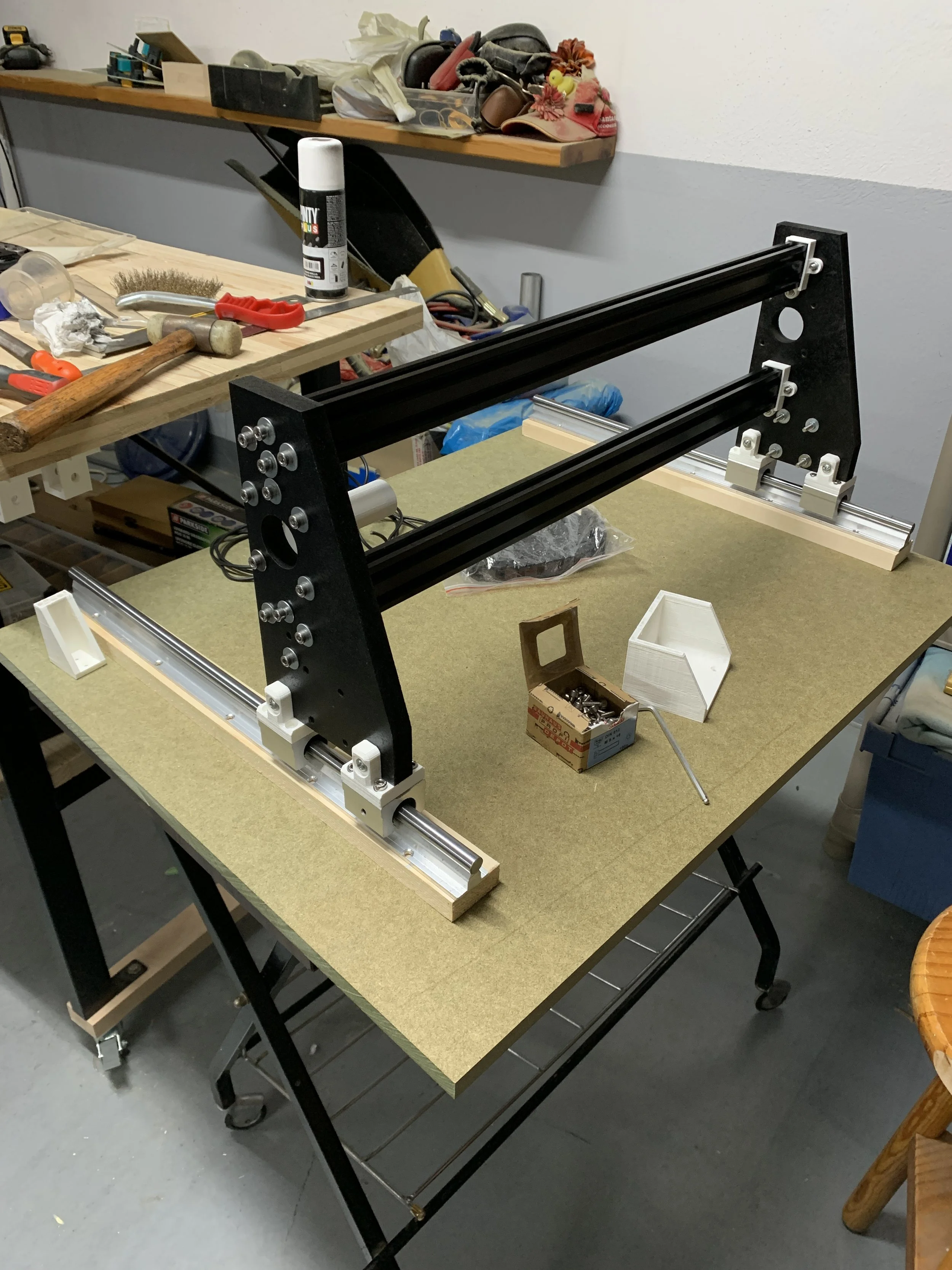
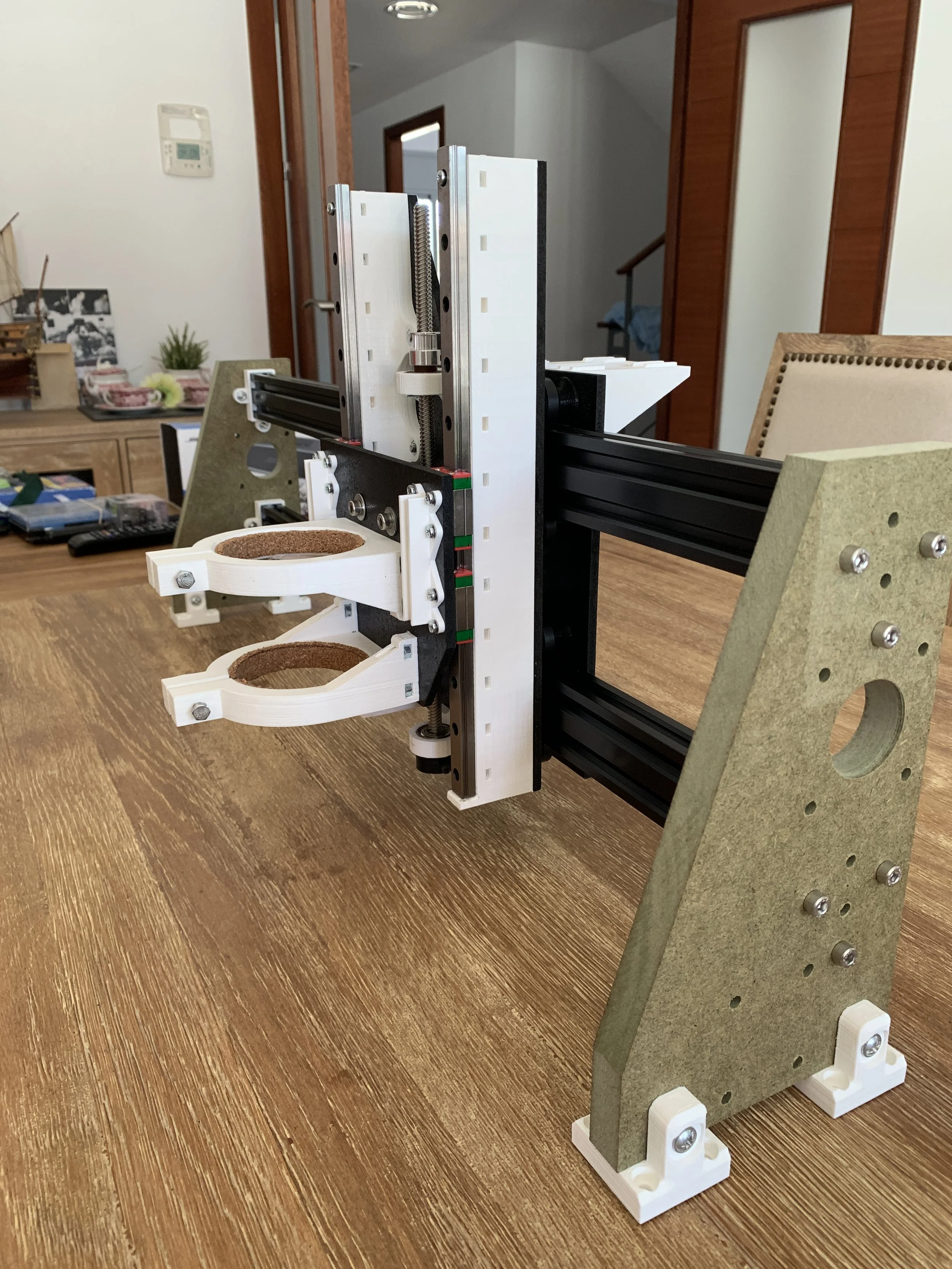
With this goal in mind, I made the CAD design for the first prototype.
Time to manufacture and assemble
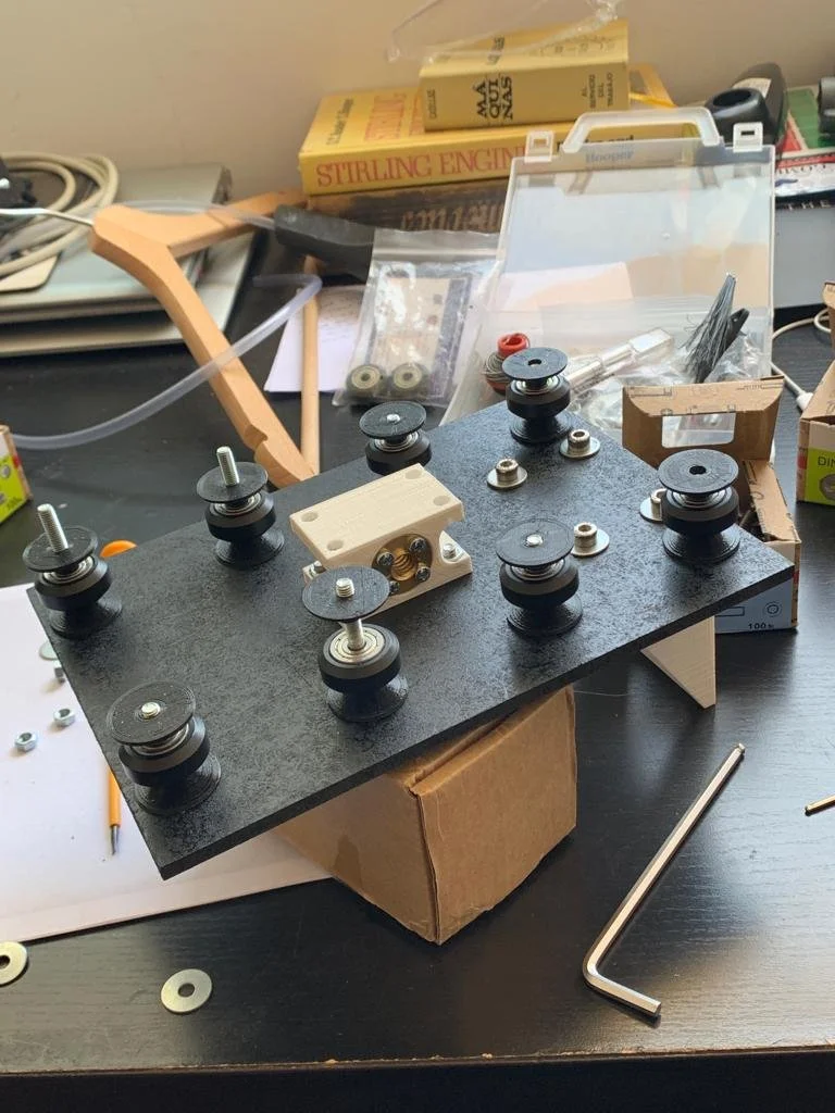
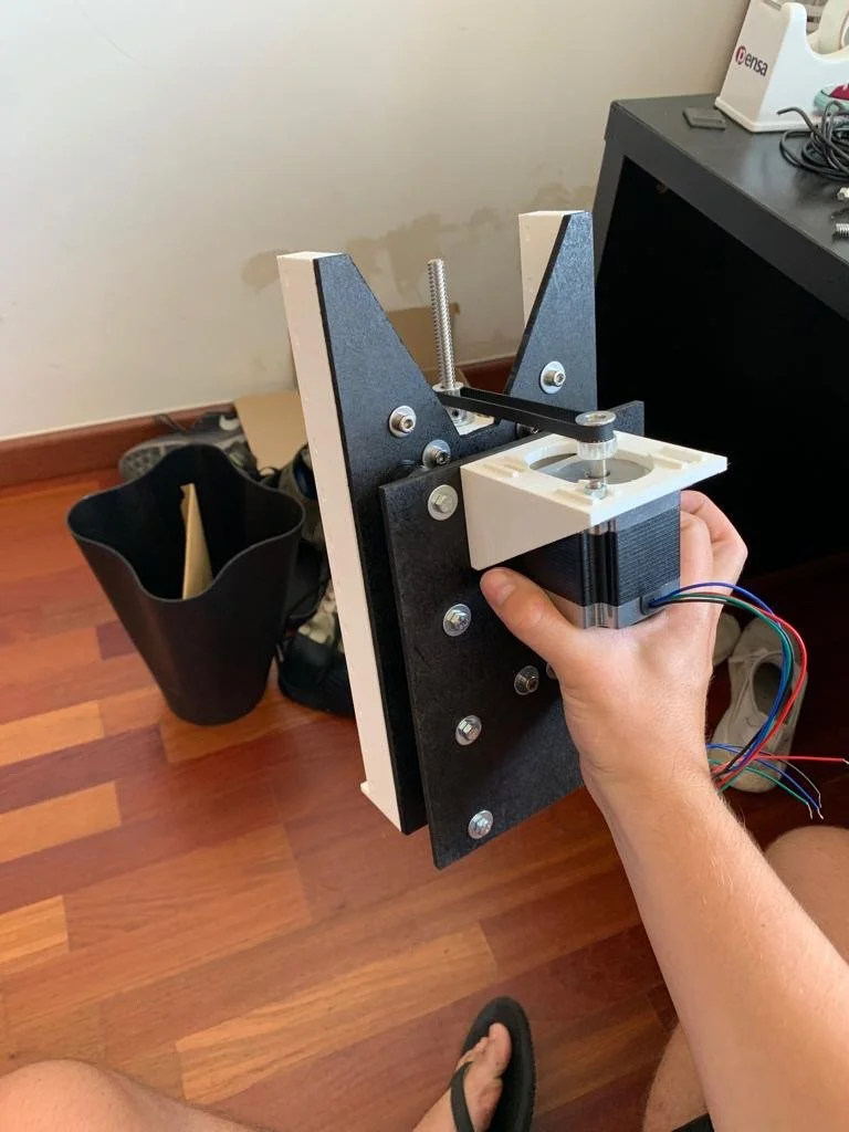
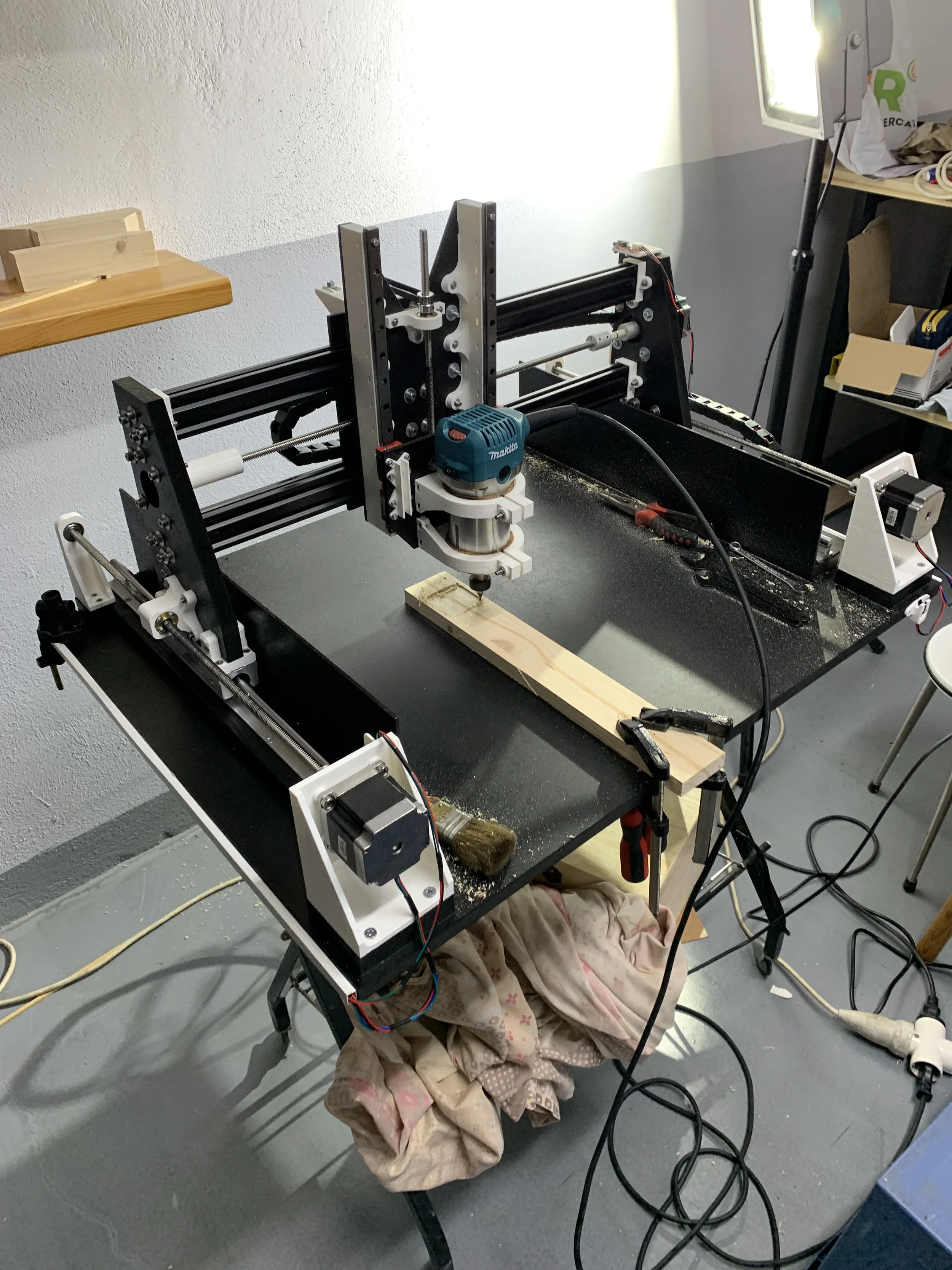
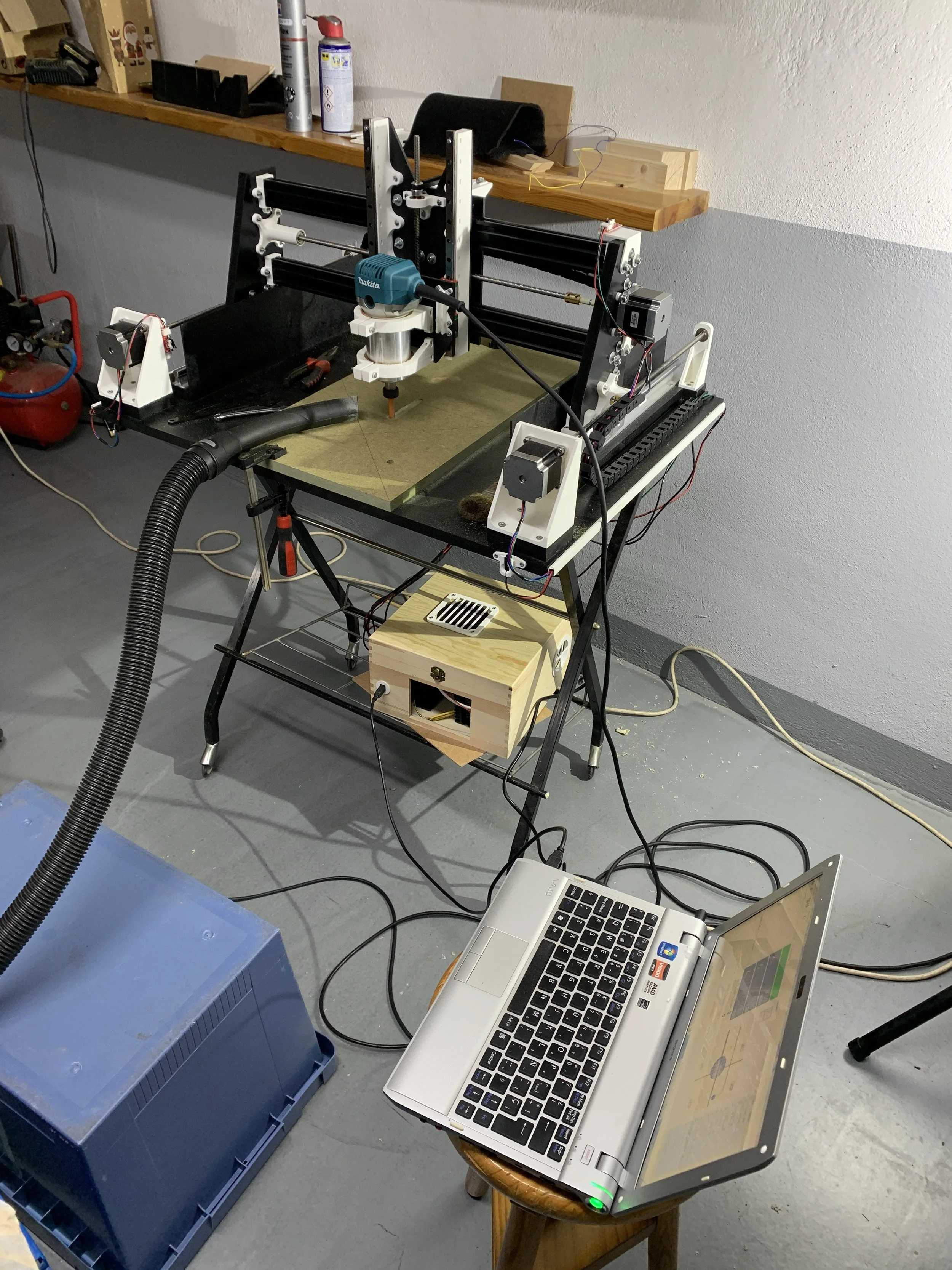
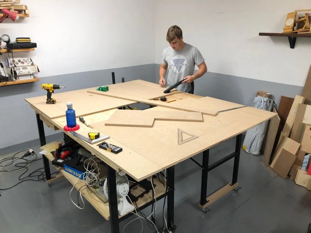
To build this first prototype I used MDF wood and 3D-printed PLA parts.
It was designed to operate with lead screws and had a working surface of 500x400 mm.
Once I had acquired all the knowledge about how a CNC machine worked, I decided to design a new more professional model, this time focusing also on the commercialization aspect of it.
And this is how
Millex CNC was born
I created Millex CNC, a new Startup that was willing to revolutionize the maker’s community. Its main goal was to provide the user with the necessary tools to create freely within a budget.
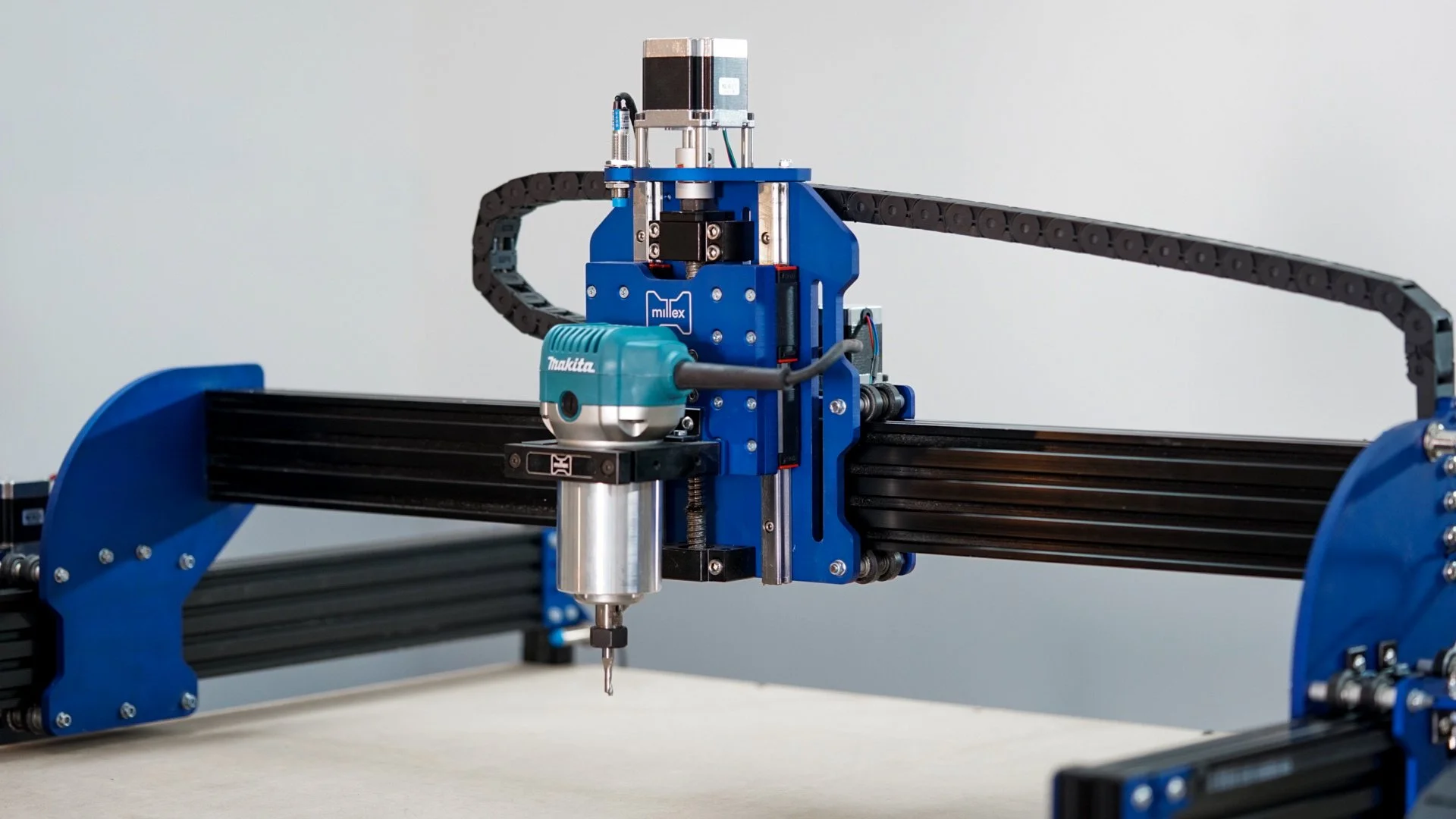
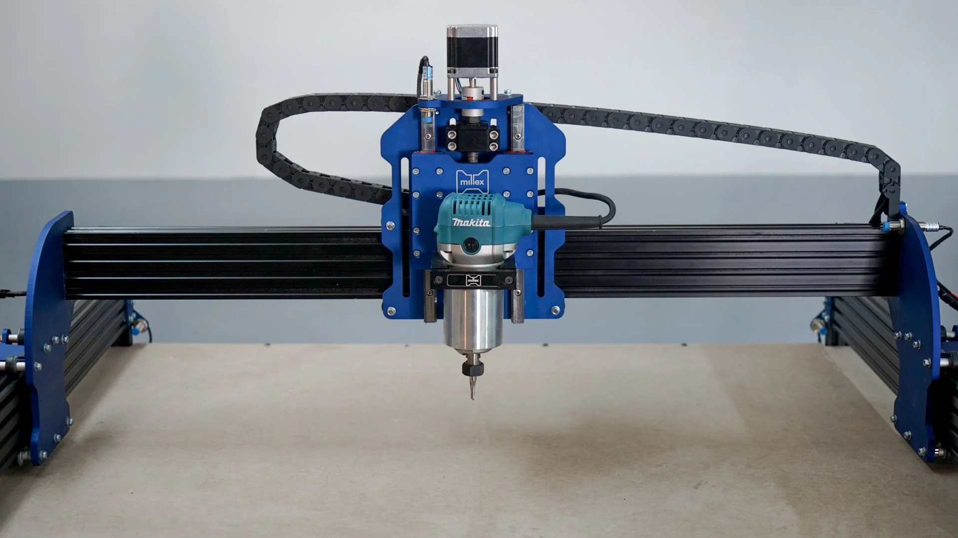
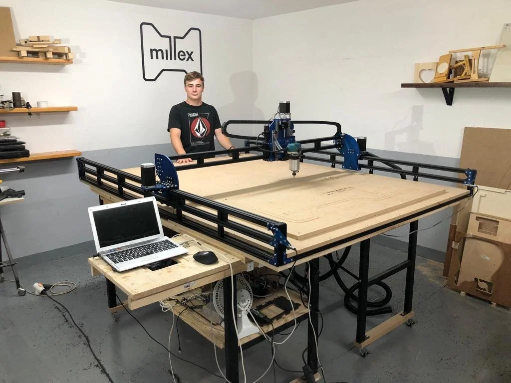
I created a high-performance, versatile, and precise CNC router machine at an affordable price that allowed makers to produce objects from their tabletop without limit.
The manufacturing process
The structural parts I designed for this machine came from 3/5/8 mm thick aluminum sheets. These parts were intended to be cut with a laser cutter, although a water jet cutter was used for the prototype. This is because the price of producing a single unit of these parts was much higher with the laser cutter than with the water jet cutter. On the other hand, for medium and large production batches it is much more cost-effective to use a laser cutter because they are much more precise and can move faster, thus reducing production costs.
Once the pieces were cut, they were sandblasted with glass microspheres to obtain a homogeneous, satin finish.
The next step was to anodize all the pieces in the company's distinctive blue color, giving them an elegant, high-quality finish.
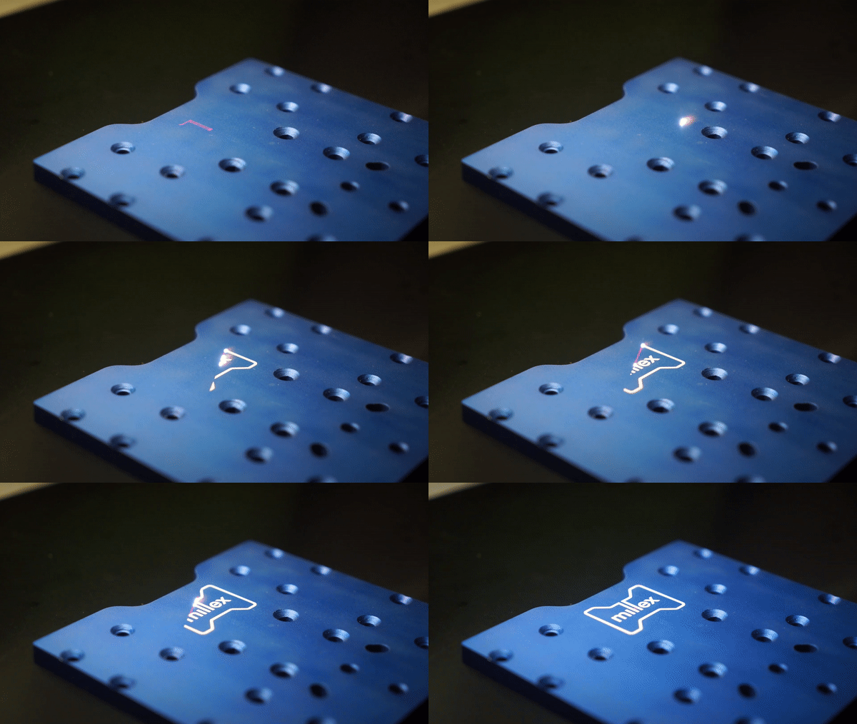
Finally, the last step was to engrave the logo on one of the central parts of the machine with a fiber laser.
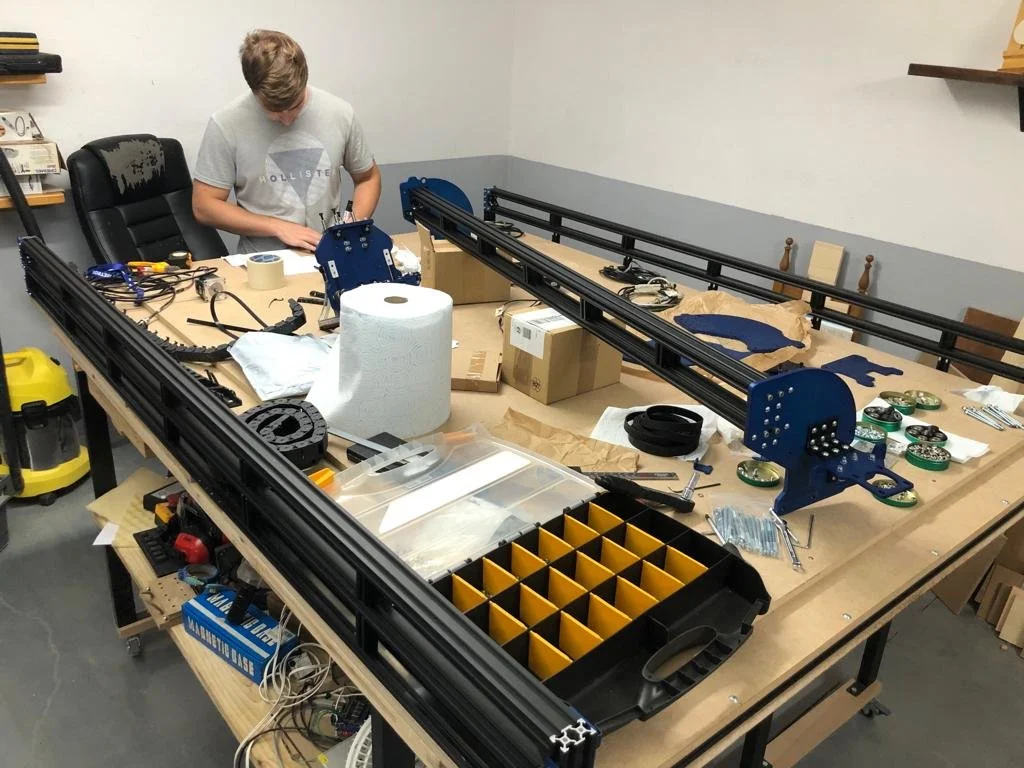
The assembly process
Design of a custom PCB
Some features:
The machine is equipped with:
Four Nema 23 stepper motors
Four Inductive proximity sensors (PNP N/C)
One ball screw to ensure Z-axis translation
Three 15 mm wide reinforced nylon belts to guarantee the translation of the X and Y axes
Linear rails for the Z-axis displacement
Software used
Fusion 360 - Autodesk
Universal Gcode Sender
Size customizable
I designed the machine to be versatile, i.e. it adapts to the user's needs. It is designed in such a way that it can be assembled in different size combinations. Therefore, if one day it is decided that a larger working surface is needed, it is as easy as changing the aluminum profiles and a few other parts to enlarge the machine.


